
Technical question: How does hydrocyclone inlet pressure affect separation cut size and underflow condition, and how should the feed pump be matched for a desander or desilter?
Direct answer: Hydrocyclone inlet pressure controls the tangential velocity that drives centrifugal separation. Below the manufacturer’s operating window, separation weakens and the effective cut size usually rises; excessive pressure increases throughput, wear and fluid loss without guaranteeing a proportionally finer cut. Match the feed pump at the real mud density, viscosity, piping head and cyclone demand, then verify manifold pressure and underflow condition in operation. Treat pressure as one controlled variable alongside cone geometry, feed solids, flow distribution and discharge condition—not as an independent performance guarantee.
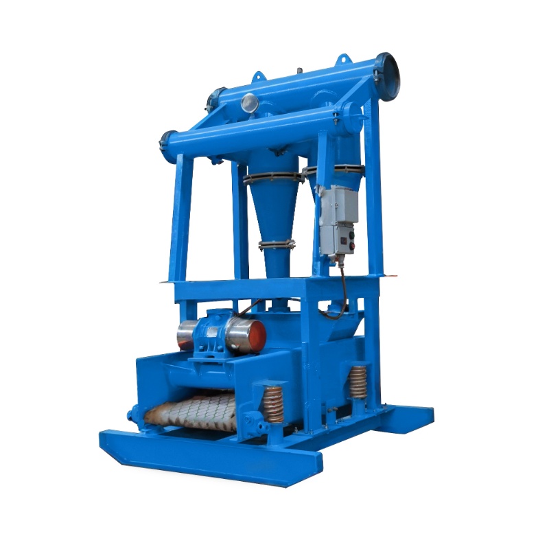
Why pressure changes separation
The inlet converts pump energy into tangential velocity. Within the manufacturer’s tested range, greater pressure drop generally increases centrifugal acceleration and throughput, which may reduce the effective cut size. The response is not linear and cannot be separated from cone diameter, inlet and apex geometry, mud viscosity, density, solids concentration and discharge condition. Use the approved cyclone curve rather than a universal pressure target.
Inputs required before calculation
- Required process flow and operating/maximum circulation rates
- Mud density, viscosity or representative rheology, temperature and solids loading
- Cyclone diameter, quantity, inlet/apex/vortex geometry and supplier operating window
- Suction level, elevation, pipe length/diameter, fittings and manifold distribution
- Discharge backpressure, underflow handling and downstream screen capacity
- Weighted-mud program and acceptable barite or liquid loss
- Pump and motor curves, efficiency, speed range and NPSH data
Calculation sequence
1. Define cyclone pressure drop
ΔP_cyclone = P_inlet − P_outlet. Atmospheric overflow and underflow may allow a simplified outlet assumption, but any manifold, hose or discharge backpressure must be included.
2. Convert pressure demand to pump head
H_cyclone = ΔP_cyclone / (ρg). Then calculate H_TDH = Δz + h_f + H_cyclone + H_backpressure. Because pressure and head are not interchangeable without density, a denser mud changes the pump duty even when the required manifold pressure is unchanged.
3. Match flow to active cones
Use the supplier-verified flow per cone at the proposed mud and pressure. N_active = ceil(Q_design / Q_verified_per_cone). Check manifold balance; installed cone count does not prove that every cone receives the same flow.
4. Check power and suction
P_hydraulic = ρgQH_TDH. Convert to motor input using pump and drive efficiency, then apply only a documented margin. Confirm the operating point lies on the pump curve and verify NPSH_available > NPSH_required + margin at the minimum tank level.
5. Verify the cut from evidence
Do not calculate a guaranteed cut size from pressure alone. Use the cyclone manufacturer’s curve for the actual cone and fluid, then validate with a project test or particle-size samples when the cut is contract-critical.
Pump operating point, mud properties and cone selection
Higher viscosity usually reduces separation efficiency and can shift the effective cut coarser. Density affects pressure-to-head conversion, motor load and the behavior of weighted solids. Cone diameter and geometry set the basic capacity and separation range: a desander cone and a desilter cone are not interchangeable merely because the same manifold pressure is available. The selected number of cones must accept the design flow without forcing any cone outside its verified window.
Reading the underflow: spray versus rope
A stable spray with an open air core is commonly used as an operating indicator that the apex is discharging freely. A rope-shaped or dense cord can signal excessive solids loading, a restricted or worn apex, feed imbalance or an unsuitable pressure/flow point. These are diagnostic signs, not acceptance criteria by themselves. Record pressure, flow, mud properties, active cone count and apex condition before changing pressure or hardware.
Weighted mud and barite-loss risk
In weighted mud, aggressive hydrocyclone operation can discard useful barite and liquid with the underflow. A finer apparent cut is not automatically a better system result. Balance drilled-solids removal against barite recovery, dilution cost and rheology control; operate only the required cones, avoid excess pressure, and coordinate hydrocyclone use with the drilling-fluid program and centrifuge strategy.
Evidence and engineering-judgment boundary
- Calculated, Grade B: pressure drop, TDH, pipe loss, flow split, motor input and NPSH when project inputs and curves are documented.
- Supplier/test, Grade B: cone capacity and cut-performance curve for the identified cyclone and declared fluid/test method.
- Engineering judgment, Grade C: preliminary margin, maintenance response and spray/rope diagnosis before sampling or a controlled test.
- Grade A: not claimed unless a traceable witnessed test or comparable field record verifies the result.
Result and limitations
The method produces a controlled pressure window, pump duty point, active cone count, power and suction check, inspection limits and evidence plan. It does not replace the cyclone supplier’s curve, a drilling-fluid program, project hydraulic design or field verification. Abrupt changes in feed solids, gas, viscosity, temperature, apex wear or manifold balance can change performance even when the gauge pressure remains constant.
Frequently asked questions
Does higher inlet pressure always produce a finer cut?
No. Pressure must remain inside the cyclone manufacturer’s operating window. Excess pressure can increase wear, fluid loss and pump load without delivering a proportional improvement in separation.
What does a rope-shaped underflow indicate?
A rope or dense cord often indicates an overloaded apex, restricted discharge, excessive solids loading or an unsuitable operating point. Check pressure, flow, apex condition and feed properties together before changing hardware.
Is a spray-shaped underflow proof of correct separation?
No. A stable spray with an open air core is a useful operating sign, but it does not prove the required cut size. Confirm the feed conditions, cyclone curve and, when needed, sampled solids distribution.
How should a feed pump be selected for desanders or desilters?
Select the pump at the combined duty of required manifold flow, cyclone pressure head, elevation, piping loss, backpressure, mud density and viscosity. Verify the operating point on the pump curve and check motor load and suction margin.
How can barite loss be controlled in weighted mud?
Do not chase the finest possible cut by pressure alone. Use the approved pressure window, monitor underflow and mud properties, avoid unnecessary bypass through hydrocyclones, and confirm the solids-control strategy with the drilling-fluid program.
Related technical pages
Desander equipment · Desilter equipment · Cyclone feed pump · Mud cleaner · Mud-tank and pump matching · Solids-control system design